|
 |
|
 |
|
| Author |
Message |
mspaw
Community Member
Joined: 18 Mar 2007
Posts: 234
Location: Sacramento CA
|
 Posted: Tue May 17, 2011 9:22 pm Post subject: Posted: Tue May 17, 2011 9:22 pm Post subject: |
 |
|
Don-
Yep thats what Ive thought for a few years. Whats interesting though after doing 50+ of them is the choice of the 4 indents. While its not difficult to do it does take a bit of time and its a bit of an odd feature on a otherwise completely lathed part, save for the screw holes. Ive always liked the design, and its so much better as a machined part vs a casting but if I was in a rush to build the prop Its a detail that might not be warranted by the screen time it was going to receive.
-Michael |
|
| Back to top |
|
|
|
|
 |
|
 |
|
|
|
|
| Author |
Message |
Vader
Community Member

Joined: 19 Feb 2011
Posts: 267
Location: Sweden
|
| Posted: Wed May 18, 2011 7:09 am Post subject: |
|
|
| DonParker wrote: | | If I were to make one out of the existing screwdrivers in the above link, I would just chuck it in the lathe and turn the knurl off. If you used the bigger drivers and did that, you could then re-knurl it to the diamond pattern and mill the indents with a ball endmill. |
My thinking to a T.
While it is true that the part receives very little screen time for the effort (or not - IIRC it is quite visible in the shot where Deckard sneaks along the wall) ... if the story that they just smacked it on the cylinder cover to hide the gap is correct, it would make sense that it just came out of the prop builder's greeblies box.
It is quite easily conceivable that he might have had this modified screwdiver lying there, left over or recovered from an earlier project, picked it up and thought that "okay this would actually fit here", and then screwed it in place.
It seems actually a bit less likely that they would have made a bespoke part for such a relatively trivial task. But if this was something they already had on hand, already modified for a role where the effort was thought to be justified...
_________________
26354 |
|
| Back to top |
|
|
|
|
|
|
|
|
|
|
|
| Author |
Message |
racprops
Community Member

Joined: 30 Oct 2006
Posts: 2450
Location: Phoenix AZ
|
| Posted: Wed May 18, 2011 7:30 am Post subject: |
|
|
Considering the amount of effort already put into the prop, I find doing the sight rod a drop in the bucket...
Consider the amount of work in machining the Steyr Receiver, and it fits so very well, and seemly this was only done once, no re-takes...
Consider the front cap and the working bolt with all its detailing…
Consider the grips, grip frame and butt plate and the metal handmade trigger guard.
Consider both side covers, and the use of the binding post on the right side cover.
I still think a screw driver was considered and used as a mockup, but as it needed to be hollow a new one was made.
My 2 cents worth.
Rich
_________________
I never have enough time to do all I want to do! |
|
| Back to top |
|
|
|
|
|
|
|
|
|
|
|
| Author |
Message |
andy
Community Guide

Joined: 01 Nov 2006
Posts: 6237
Location: Rochester, NY
|
| Posted: Wed May 18, 2011 1:13 pm Post subject: |
|
|
I don't find any of these possibilities implausible at all. I think it may just be exactly that. I guess my issue may be that it looks like an added on piece, and looks like a found part, rather than something that was designed to fit into style of the rest of the gun. The idea that it was used to hide the gap from the left side cylinder cover and Steyr receiver, does make total sense to me. I guess if they started out with the screwdriver, and then when everybody said "That looks like a screw driver", then they began to modify it to hide it's origins instead of looking for a new part. That could make some sense, but there is still something about that part that looks "found as-is" to me. I get a similar feeling that I had seen it before like I did with the weaver knob.
We may never know unless we can get in touch with the prop master, and/or the gun's maker. I have tried in the past, and I know a few others have talked to them, and maybe they are holding back the information. That is something that happens a lot in this hobby. Many of these guys are in the business, and have much better connections to the industry and agencies than the rest of us do.
I still think there are a lot of unsolved mysteries left with this prop. That is why I think I am still so intrigued by it after all these years. Someday I am hoping to see some other mock ups, and drawing showing concepts for the gun using the Steyr and Bulldog as we saw with Stephen Dane's sketches of the 358 COP. Some of those photos of the hero from production finally showed up when the gun went for auction. Photos that I know some people on the RPF had already seen, but were not willing to share. I have a feeling there is a lot more, we just have to talk to the right person to find it.
Andy |
|
| Back to top |
|
|
|
|
|
|
|
|
|
|
|
| Author |
Message |
SCOFFMAN
Community Member

Joined: 23 Mar 2008
Posts: 126
Location: Spokane, WA
|
| Posted: Thu May 19, 2011 1:07 am Post subject: |
|
|
What about some sort of hollow punch? I have a set and the shape and knurling is pretty close and there's already a slot cut into it on one side where the punched material is ejected. The ones I have wouldn't make for an exact match, but I know there's been more than one design over the years...
_________________
Fiery the angles fell, deep thunder rolled around their shores, burning with the fires of Orc. |
|
| Back to top |
|
|
|
|
|
|
|
|
|
|
|
| Author |
Message |
DonParker
Community Member
Joined: 09 Jan 2009
Posts: 250
|
| Posted: Sat May 21, 2011 3:51 pm Post subject: |
|
|
I just was searching through my toolbox and low and
behold I have those screw drivers. I'd just forgot about
them. Seeing them in person I'd say that they are a good
match for a sight rod. I still stand by the turning off of the
knurl, but I think the diamond knurl may have been a
seperate peice and just pressed on.
Don |
|
| Back to top |
|
|
|
|
|
|
|
|
|
|
|
| Author |
Message |
Robotprops
Community Member

Joined: 11 Apr 2010
Posts: 280
Location: Vancouver, B.C.
|
| Posted: Sat Mar 23, 2013 3:14 am Post subject: |
|
|
I'm not one to let an idea go.
I think it's what draws me and people like me to our little community.
As a Prop Master and sci-fi fan I, like you, pay attention to details.
Recently I did a shoot that brought this thread back to mind.
Something clicked. I re-read this thread that I started and another from a few years ago from Noeland:
http://propsummit.com/viewtopic.php?p=9866&sid=4a28aded8f68117c36df03e9a0ef0765
In that thread amish mentioned dental tools as being the base for the sight rod. This idea was glossed over in favor of the idea that the rod was a jewelers screwdriver or that it was custom made. I myself was convinced that a small driver was the ticket.
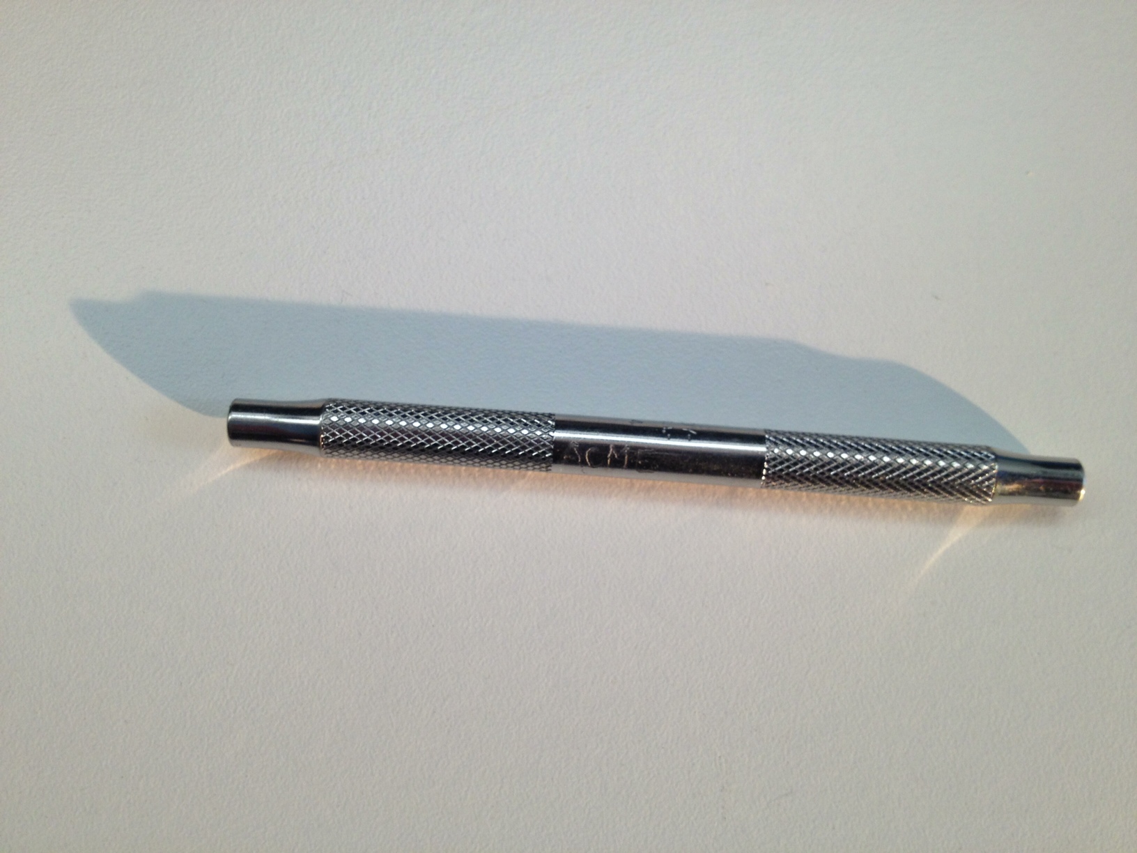
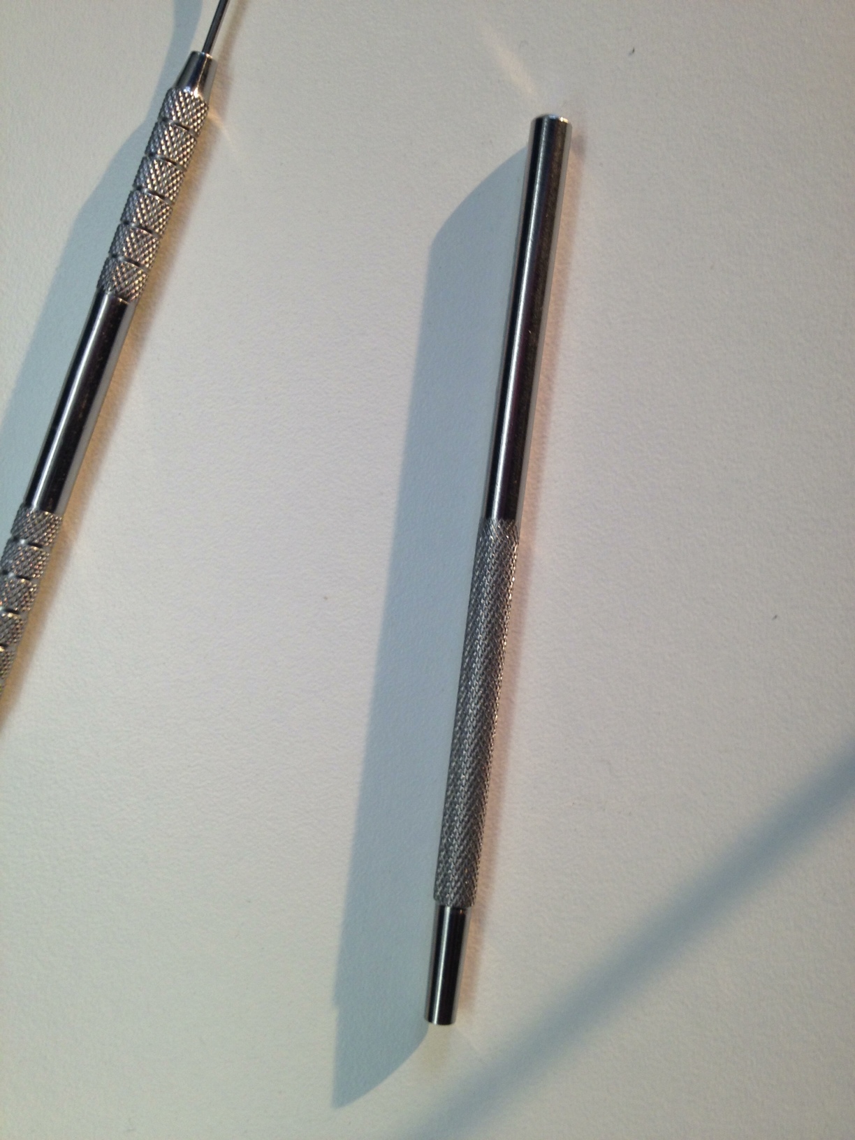
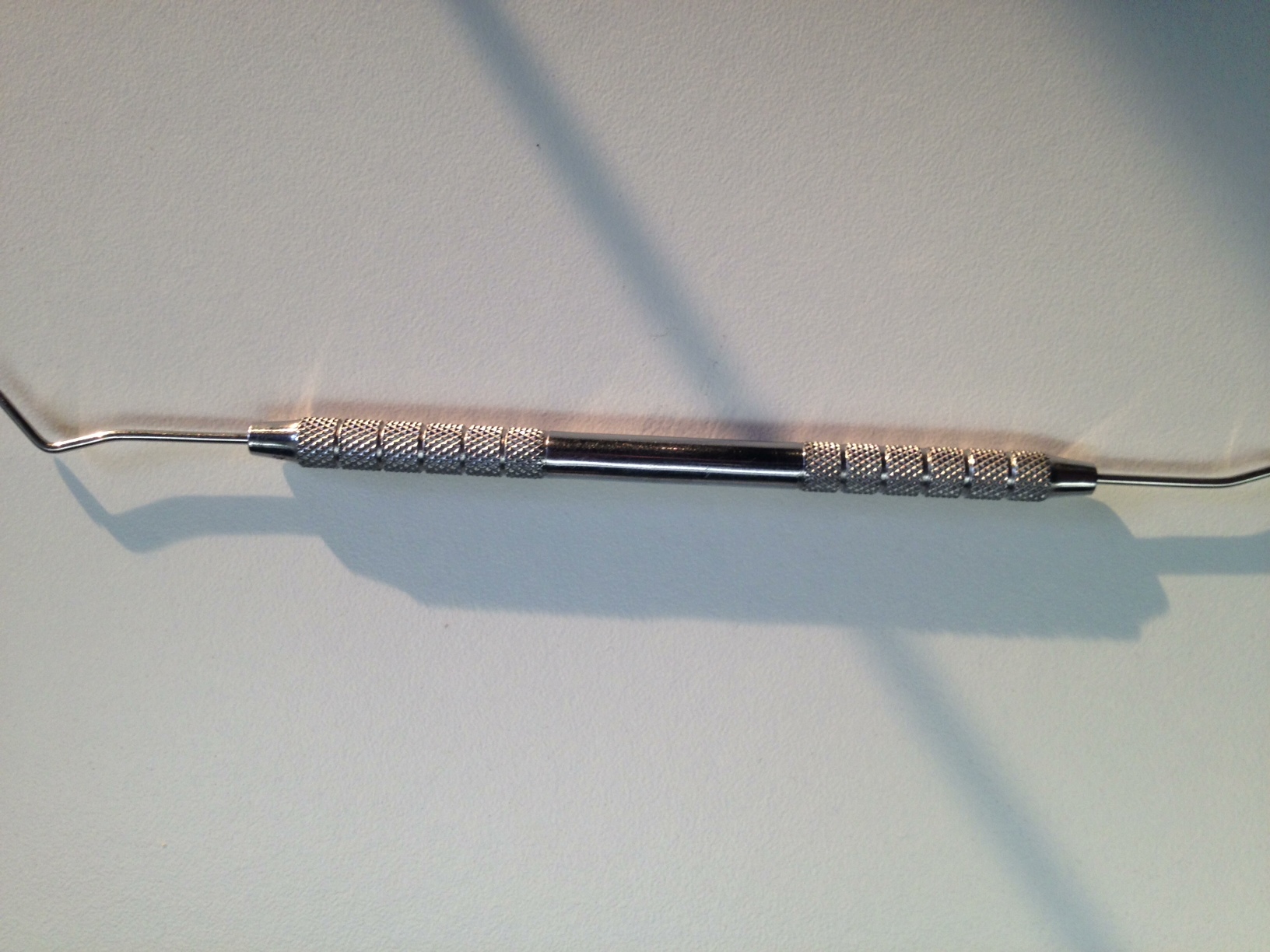
In that thread, there was discussion about being able to read "Made in USA" on the rod in one of the indents. This kept me wondering. So much of this blaster was found objects. The sight rod was probably an after thought to cover seems or wires. A found object would do the job here.
My recent shoot involved dentists. I pulled some dentistry tools from my kit and looked at others that our buyer had brought forth. I was startled to see the variety of knurlings and grips that these tools were given.
I was also pleasantly surprised to see that many of them have hollow handles to allow for different tips. I now believe that some searching for vintage tools will find us the true origin of the sight rod.
These I had on hand:
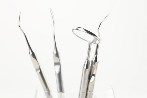
Some that I found online right away:

 |
|
| Back to top |
|
|
|
|
|
|
|
|
|
|
|
| Author |
Message |
ocd
Community Member
Joined: 24 Nov 2010
Posts: 115
Location: Royal Oak MI
|
| Posted: Sat Mar 23, 2013 2:41 pm Post subject: And now for something COMPLETELY different. |
|
|
MIGHT just be the an extractor rod from a revolver.
My dad used to have a late 70's, early 80's crappy Taurus 38 that had an extractor rod that looked REALLY close. Even had the indents. It was a light weight Taurus Titanium 38.
turn it around ie the part with the knurl grips are were you pull or push.
Just a thought.
_________________
"No choice pal,..."
"Questions?,..." |
|
| Back to top |
|
|
|
|
|
|
|
|
|
|
|
| Author |
Message |
Robotprops
Community Member
Joined: 11 Apr 2010
Posts: 280
Location: Vancouver, B.C.
|
| Posted: Sat Mar 23, 2013 3:27 pm Post subject: |
|
|
| A new twist. Extractor rod eh? Worth looking into. |
|
| Back to top |
|
|
|
|
|
|
|
|
|
|
|
| Author |
Message |
joberg
Community Member
.jpg)
Joined: 06 Oct 2008
Posts: 9447
|
| Posted: Sat Mar 23, 2013 5:05 pm Post subject: |
|
|
Interesting path Robotprops...  |
|
| Back to top |
|
|
|
|
|
|
|
|
|
|
|
| Author |
Message |
veektohr
Community Member
Joined: 26 Feb 2016
Posts: 237
Location: Los Angeles
|
| Posted: Sat Feb 11, 2017 9:41 pm Post subject: |
|
|
Not a revelation or anything here, but I came across these punches.

Now imagine you're an armorer, and you're hot-rodding a revolver for Ridley Scott's new movie. It looks great, but you need something to cover up the gap on top of the left side cylinder cover. You look down at your workbench where you just happened to set one of the punches you were using to tear down / assemble the revolver...
Anybody know where to find vintage gunsmithing tools? |
|
| Back to top |
|
|
|
|
|
|
|
|
|
|
|
| Author |
Message |
joberg
Community Member
Joined: 06 Oct 2008
Posts: 9447
|
| Posted: Sun Feb 12, 2017 11:23 am Post subject: |
|
|
| Could be veektohr, could be. Looking at the previous posts, it could be fairly easy to machine the hollow spacers in those rods. |
|
| Back to top |
|
|
|
|
|
|
|
|
|
|
|
| Author |
Message |
racprops
Community Member
Joined: 30 Oct 2006
Posts: 2450
Location: Phoenix AZ
|
| Posted: Sun Feb 12, 2017 11:59 am Post subject: |
|
|
Personally I think the side rod was INSPIRED by some old jewelers/watch repairman’s screw drivers, BUT as the prop maker wanted a hollow rod he just machined it up.
Using the screwdriver body as a guild.
You just find some hollow rod and start machining.
After I have made a few myself and it is not all that hard to do.
Rich
_________________
I never have enough time to do all I want to do! |
|
| Back to top |
|
|
|
|
|
|
|
|
|
|
|
| Author |
Message |
Shai`tan
Joined: 25 Oct 2017
Posts: 5
|
|
| Back to top |
|
|
|
|
|
|
|
|
|
|
|
| Author |
Message |
andy
Community Guide
Joined: 01 Nov 2006
Posts: 6237
Location: Rochester, NY
|
| Posted: Sat Oct 28, 2017 3:48 pm Post subject: |
|
|
That type of cross cut spiral machining is a pretty common thing on a ton of different tools. It is the rest of the details that are eluding us. As far uploading photos, I know there was a tutorial on here somewhere. I may have to post a new one soon. You can use the upload manager here to load pics, but you need to copy and paste the links into your messages. The tags can help them be visible without clicking, but depending on image size, it isn't always advisable to do so. I can help with that later. You can also post links to photos hosted elsewhere as well just by posting the images url address. hope that helps get you started.
Andy |
|
| Back to top |
|
|
|
|
|
|
|
|
|
|
|
| Author |
Message |
Shai`tan
Joined: 25 Oct 2017
Posts: 5
|
| Posted: Sat Oct 28, 2017 5:49 pm Post subject: |
|
|
| Thx for the info. |
|
| Back to top |
|
|
|
|
|
|
|
|
|
|
|
|
You cannot post new topics in this forum
You cannot reply to topics in this forum
You cannot edit your posts in this forum
You cannot delete your posts in this forum
You cannot vote in polls in this forum
|
|
|
|
|
|
|
|