|
 |
|
 |
|
| Author |
Message |
delorean
Community Member

Joined: 25 Feb 2008
Posts: 12
Location: Fraser Valley, BC
|
 Posted: Mon Feb 25, 2008 8:29 pm Post subject: Wiring diagram need for PKLager Katsumata-D Posted: Mon Feb 25, 2008 8:29 pm Post subject: Wiring diagram need for PKLager Katsumata-D |
 |
|
Having some troubles with my kit as it never came with instructions. I am guessing that the 2 long bolts are for the grip. 2 half-inch screws, No clue! 2 smaller hex screws but smaller. The sidkit seems to come with a resistor but this kit does not. If the instructions are on the site somewhere, just reply with a thread or link. Thanks
John  |
|
| Back to top |
|
|
|
|
 |
|
 |
|
|
|
|
| Author |
Message |
darkknight0667
Community Guide

Joined: 11 Apr 2006
Posts: 799
Location: Land O Lakes, FL
|
| Posted: Tue Feb 26, 2008 6:24 am Post subject: |
|
|
I doubt if the instructions are here, but Rick Ross (the original designer/builder) is a member (and a heck of a nice guy to boot). Just PM him and I'm sure he'll find a way to get them to you.
_________________
Pete |
|
| Back to top |
|
|
|
|
|
|
|
|
|
|
|
| Author |
Message |
hirohawa
Community Member
Joined: 18 May 2006
Posts: 1067
|
|
| Back to top |
|
|
|
|
|
|
|
|
|
|
|
| Author |
Message |
delorean
Community Member
Joined: 25 Feb 2008
Posts: 12
Location: Fraser Valley, BC
|
| Posted: Tue Feb 26, 2008 5:52 pm Post subject: Switch location |
|
|
| Thanks for the wiring theory on LEDs. That will greatly help out. Will have to calculate the R value for 4 LEDs in series. The switch mount is then all I need to figure out for the kit. Rick has in the meantime the info to determine the type of kit I have in my possession. That will help out on the assembly as the hex-bolts will need to go somewhere. |
|
| Back to top |
|
|
|
|
|
|
|
|
|
|
|
| Author |
Message |
doppelganger01
Community Member

Joined: 05 Nov 2006
Posts: 229
Location: L.V.N.V.
|
| Posted: Tue Feb 26, 2008 5:58 pm Post subject: |
|
|
Hi John,
Sorry for the delay in finding this instruction sheet. From what you have described to me, I believe you have a version of my PKD-II 2018 Model that sadly I no longer offer. However, I was able to locate the following wiring sheet that went with my kit. I hope you find it helpful.

The bolts you described are still a mystery to me. The image you PM'd me did not show up. Could you post it here?
Rick
_________________

www.reddragonkipplecompany.com
www.pflagerkatsumata.com
www.ricklross.com |
|
| Back to top |
|
|
|
|
|
|
|
|
|
|
|
| Author |
Message |
delorean
Community Member
Joined: 25 Feb 2008
Posts: 12
Location: Fraser Valley, BC
|
| Posted: Wed Feb 27, 2008 3:32 am Post subject: Fantastic diagram |
|
|
I would have to make a correction. I do have 5 LEDs in the package. I was not sure where LED #5 would go on the blaster. The diagram does not tell me the location of the switch mount. I have so far done a great job on the finish with gun-metal and clear flat. I would have to post the pic once done.
 |
|
| Back to top |
|
|
|
|
|
|
|
|
|
|
|
| Author |
Message |
delorean
Community Member
Joined: 25 Feb 2008
Posts: 12
Location: Fraser Valley, BC
|
| Posted: Wed Feb 27, 2008 4:27 am Post subject: Polarized version correct? |
|
|
I have attached polarized version of the diagram and correct me if I am wrong. The + lead feeds all - LED leads and the - lead feeds all + LED leads. If parallel circuit is safe with LEDs I will continue with this hook-up. I was always under the impression that serial hook-up was required with LEDs to prevent them from blowing up.
SERIES CIRCUIT: Voltage divides across components ( current is constant)
PARALLEL CIRCUIT: Current divides across components ( voltage is constant)
If the LED can only handle 2V, I wonder if the 3V output from the 2 AAA batteries will cause a problem. The total current output is divided across the 5 LEDs. If 15 mA is required for each LED, 75 mA is necessary from the AAAs. If you connect a LED across a battery, it will blow because the current is exceeding 15mA.
Rick, I will still continue with your diagram instructions. If it was done without a resistor, it should be safe. Will test on the bench today.

[/img]
Last edited by delorean on Wed Feb 27, 2008 3:56 pm; edited 1 time in total |
|
| Back to top |
|
|
|
|
|
|
|
|
|
|
|
| Author |
Message |
doppelganger01
Community Member
Joined: 05 Nov 2006
Posts: 229
Location: L.V.N.V.
|
| Posted: Wed Feb 27, 2008 7:16 am Post subject: |
|
|
Hi John,
Yes. You are correct. For the PKD-II 2018, I wired them in parallel so the total required voltage would be 2V for the 5 LED's. I relied on the resistance of the wires rather than putting in a resistor for each LED. Since that time however, I learned that it is better to wire the LED's in Series with one resistor. When you do it this way you have to add the volts for the 5 LED's. The total required voltage is 10V. Unfortunately, my knowledge of electronics is limited to this. I followed the same directions that you found on the internet for LED's
I recommend that you follow the directions from the LED site and wire them in series with 1 resistor. You will need to recalculated the required voltage and change the batteries to accommodate.
I do not know the history of the kit you show in the photo. I can only say that it was not cast by me. It is, however, cast from one of my original kits. The location of the switch should be on the left side of the assembled gun, just above the "SDC - N. America" brand. It is possible that this kit is an EDC version. In 2002 I sold them all of the molds for this model.
I hope this information will help.
Sincerely,
Rick
_________________
www.reddragonkipplecompany.com
www.pflagerkatsumata.com
www.ricklross.com |
|
| Back to top |
|
|
|
|
|
|
|
|
|
|
|
| Author |
Message |
Noeland
Community Guide
Joined: 24 Oct 2006
Posts: 1328
|
| Posted: Wed Feb 27, 2008 11:38 am Post subject: |
|
|
Yeah, I've seen that kit on ebay recently. Not sure it's EDC though, but it's definately a recast. I don't think chip retooled anything, and this looks retooled.
I have to admit, without your diagrams Rick, I'd be totally lost!  hahaha. I'm just horrible with electronics and wiring. hahaha. I'm just horrible with electronics and wiring.
But I'm trying!
Delorean, any other pics of the kit? This looks like the same one that's on ebay. Love to see some more detailed shots.
_________________
I don't have enough blasters! |
|
| Back to top |
|
|
|
|
|
|
|
|
|
|
|
| Author |
Message |
delorean
Community Member
Joined: 25 Feb 2008
Posts: 12
Location: Fraser Valley, BC
|
| Posted: Wed Feb 27, 2008 2:18 pm Post subject: Challenge is there! |
|
|
Yah guys, the kit is one of those listed on Ebay by Rick Clark in Australia. If anybody is worried about customs, this kit will 100% fly thru easy. The wiring I can deal with, the switch however, as Rick mentioned its location, will not fit in the square cavity just below the # 826354. The switch is much longer than the 1/2 inch hole. Back to the drawing board and find a place for the switch.
.jpg) [/img] [/img]
Last edited by delorean on Thu Feb 28, 2008 3:14 am; edited 2 times in total |
|
| Back to top |
|
|
|
|
|
|
|
|
|
|
|
| Author |
Message |
delorean
Community Member
Joined: 25 Feb 2008
Posts: 12
Location: Fraser Valley, BC
|
| Posted: Wed Feb 27, 2008 2:24 pm Post subject: Mor pics to follow! |
|
|
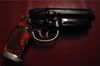
| I had some really trouble with the finish but after priming, I switched to Tamiya Color Gun Metal and a coat of clear flat. The brush-on chrome I tried but not happy with the final look. I decided to do the entire gun in Gun Metal with the exception of the triggers. It will look just like the Off World from that other thread about which blaster to refinish. I also have one of those sitting at the border. Will have to pick it up one of these days! |
|
| Back to top |
|
|
|
|
|
|
|
|
|
|
|
| Author |
Message |
delorean
Community Member
Joined: 25 Feb 2008
Posts: 12
Location: Fraser Valley, BC
|
| Posted: Thu Feb 28, 2008 2:06 am Post subject: First picture |
|
|
Once I had primer applied, I was told to use a semi-gloss but i did not like the finish one bit. I decided to give it a light sanding and apply gun-metal. The finish turned out okay but wanted a much flatter appearance so I sprayed flat-clear and this was the result of that $40 paint-job. I used Krylon Original chrome for the grip but needed to give it another coat. It will be 2 weeks once this thing is assembled. I am VERY picky on detail so if I see anything wrong, I repaint until it is perfect.
.jpg) [/img] [/img]
_________________
As Rutger would say in his native Dutch: " Ik heb dingen gezien die jullie niet kunnen geloven!"
Floris, a replicant in tights |
|
| Back to top |
|
|
|
|
|
|
|
|
|
|
|
|
You cannot post new topics in this forum
You cannot reply to topics in this forum
You cannot edit your posts in this forum
You cannot delete your posts in this forum
You cannot vote in polls in this forum
|
|
|
|
|
|
|
|