|
 |
|
 |
|
| Author |
Message |
Buch
Community Member

Joined: 27 Feb 2014
Posts: 1184
Location: Copenhagen, Denmark
|
 Posted: Sat Apr 15, 2017 4:21 am Post subject: Posted: Sat Apr 15, 2017 4:21 am Post subject: |
 |
|
What kind of tool did you use to round the corners of the main case? Love the progress 
_________________
Monsieur, azonnal kövessen engem bitte |
|
| Back to top |
|
|
|
|
 |
|
 |
|
|
|
|
| Author |
Message |
8th_Passenger
Community Member

Joined: 28 Nov 2009
Posts: 443
Location: Hertfordshire, UK
|
| Posted: Sat Apr 15, 2017 5:52 am Post subject: |
|
|
Buch, I used a router.
Colin
_________________
Ripley: What's it key on?
Ash: Micro changes in air density. |
|
| Back to top |
|
|
|
|
|
|
|
|
|
|
|
| Author |
Message |
Buch
Community Member
Joined: 27 Feb 2014
Posts: 1184
Location: Copenhagen, Denmark
|
| Posted: Sat Apr 15, 2017 10:04 am Post subject: |
|
|
| 8th_Passenger wrote: | Buch, I used a router.
Colin |
Thanks  Slowly building up my tool supply and familiarizing myself with new tools... Slowly building up my tool supply and familiarizing myself with new tools...
_________________
Monsieur, azonnal kövessen engem bitte |
|
| Back to top |
|
|
|
|
|
|
|
|
|
|
|
| Author |
Message |
8th_Passenger
Community Member
Joined: 28 Nov 2009
Posts: 443
Location: Hertfordshire, UK
|
| Posted: Sat Apr 15, 2017 3:39 pm Post subject: |
|
|
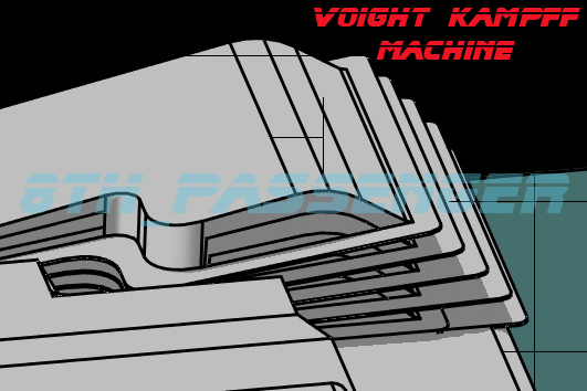
Buch, I should have said I used a round over cutting bit with a follow wheel. Two actually. I put a larger radius on the base.
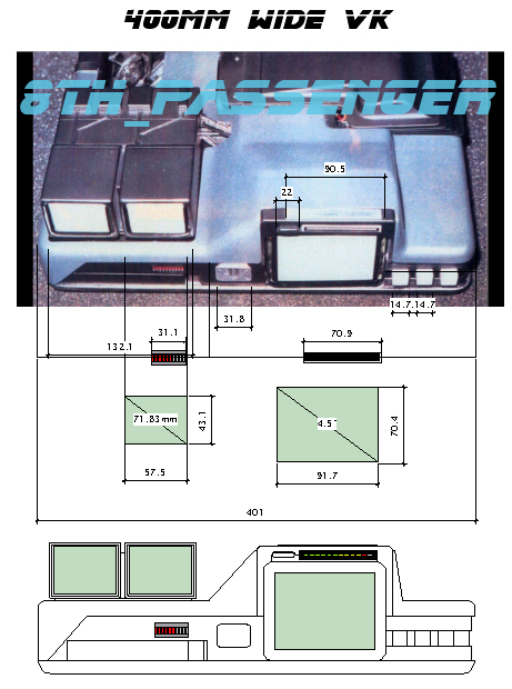
So today I choose the 400mm machine from the previous post to expand into a plan view to see if the arm sizes from my 430mm unit could be made to fit. It did.
However there are still things that don't sit right.
Having said 360mm was too small I'm now offering a unit that's 328mm wide.
Here's why.
1) This unit is supposed to fit into a briefcase and at 400mm wide this still feels too big.
2) The size of the LED Graph Bars. Have they got smaller since 1980?
3) | Quote: | | The main monitor was a color monitor used in television cameras as a viewfinder. (Not the home video kind, but the big $100,000.00 TV Studio cameras.) Not sure of the origins of the smaller ones, but I suspect they are smaller, cheaper B&W viewfinder monitors as well. |
See quote at end of post.
The Sony KV-4000 3.7" portable micro color TV I mentioned last time may be a product of the $100,000 Studio camera. Or at least the same technology.
4) Syd Mead says in Cinefex
| Quote: | | "Sony had just come out with about a one-and-a-half-inch diagonal color screen for the eyepiece monitor in their cameras". |
It had occurred to me that the screens could be viewfinders.
5) I think the three buttons could be 12mm square.
So I projected this info onto the image below and it works pretty well. The graphics of course are smaller than the size stated by Tom Southwell.
The smaller monitors could be 1.5' to 2' with the space available.
Two contenders from the period for the small monitors are (but not viewfinders):-
Panasonic TR-1000P Tr-1010P 1.5" black & white
Sanyo TMP 2170 2" black & white

Point 3) is taken from this post. I don't know who Gene is as I wasn't a member when it was originally posted. It's an interesting read.
| GKvfx wrote: | I've been involved in a couple of attempts to recreate the VK. One didn't get too far due to ...... well, due to the stuff that happens on boards. Another attempt took a weird left turn and turned into a different project altogether (I'll let them talk about it if they wish.)
But we did get some interesting tidbits of info from some of the EEG guys that worked on the thing. Some of that has filtered down already, but I'll sum it up here..........
The case was (I believe), just something they picked up at Apex or C&H Sales and, as such was ex-military or ex-industrial.
The first attempt at the VK fell apart in front of Ridley and Michael Deeley during a review. Since another group of guys, based out of EEG (and sometimes using EEG crew) were building props (like the Vid-Phones, the Espers, the Spinner cockpit, etc), it was thrown to them with a three-day deadline. The Conference Room interrogation were the first interior sets filmed and this caused a whole slew of problems since it included some ambitious Front Projection, this crazy VK prop, etc.....
I had thought that a Halliburton case may have been used to make the base of the VK. The bottom of it has the characteristics of a rounded edge - like they took a top from a Halliburton case and trimmed it down. That was NOT the case. The entire thing - top to bottom - is manufactured in the shop. Most of it is vac-form styrene. It was easy (for them) to cut some MDF (or whatever), route the edges, and then vac-form over that.
The eye uses some found parts from a "box o' crap" they pulled from Apex and C&H Sales, as well as some leftover parts from the first attempt. I think I see some Tamiya parts on there, but need to re-check this. Use of kit parts was minimal, though.
The "tray" that swings out, which I thought came from some industrial dispenser of some sort, was manufactured by EEG.
The bellows were initially motorized and designed to work with a little sound detector that would make them pulsate to the dialog on set. Given the fact that any problems with the VK would tie up the entire First Unit of the show (Ridley, Harrison, Sean, Jorden Cronenweth, etc) Ridley just asked them to rig something simple and reliable. For that, a hole was drilled through all the bellows save the top one. Each bellow was connected to the one below it with a piece of elastic string (or a spring - I forget which), and a rod was glued to the inside of the top bellow. When the operator pushed the rod up, the top bellow moved, followed by the ones beneath it. When the operator lowered the rod, the elastic took up the slack. This required the operator to be under the table during the scene and a hole drilled in the table. It was reliable. But unfortunately, since the bellows were all from the same master, they didn't nest well and they can be seen hanging up on one another as they moved. This drove the prop guys nuts, but Ridley was OK with it.
The rest of the VK was "driven" by a control box with a mass of cables coming out of it and going into the VK. (Not sure if they drilled another hole in the table to conceal this. I'll have to ask.) This controlled the arm as well as the video signals to the three monitors. The main monitor was a color monitor used in television cameras as a viewfinder. (Not the home video kind, but the big $100,000.00 TV Studio cameras.) Not sure of the origins of the smaller ones, but I suspect they are smaller, cheaper B&W viewfinder monitors as well.
The boxes housing the small monitors are just styrene boxes. The monitor tubes were pulled out of their housings and stuck in those.
Here's where it gets tricky. Photos show two vac-form shells for VK on the bench, but ALL the EEG guys claim there was only ONE VK. After all, it was built in three days and that was pushing it just to get the one done. But in looking at the movie, and has been mentioned here, there are clearly two different VK's - the one on the table and one used in closeups. I think we figured it out. Last summer, I cataloged a crew member's BR stuff prior to it being consigned to the Profiles in History auction. In there were a whole pile of photos/slides/transparencies purported to have been taken for the Esper sequence. Problem is, none of it matched up with what is in the film. They match what was published in Cinefex, but they are not in the film (save for one, actually). Turns out this stuff (shot on the first day of filming, while the problems with the Front Projection rig and lighting were being sorted out) DID make it into an early cut of the film. (In fact, you can see it on the "deleted scenes" disc.) Dissatisfied with the footage, Ridley had it all re-shot and re-transferred to video during post production in England. Once that was done, he then re-shot all the closeups of the Esper while in London. This entailed having the Esper unit prop shipped to London for the reshoot. When it was rebuilt in London, some different parts were added to it, changing the look of the thing. Looking at these shots, the VK is clearly visible in front (or part of?) the Esper. This coincides with what one of the EEG crew mentioned to me - they got a call one day to ship the VK to Ridley's office and that was the last anyone saw of it. Years later, Ridley didn't even recall making the request, so the crew member thought the thing might have been intercepted and stolen. It appears that it did make it to Ridley's office, and it did make it to London, Ridley just forgot. (Where it is now is anyone's guess, but my money is that it is in London.)
So what does the Esper have to do with the VK? Since they reshot the Esper, they also probably reshot close-ups of the VK screens. And, in the new Esper sequence, the VK monitors have signals running to them. Since all that footage was likely remastered in PAL format (not NTSC), they would have to have changed the monitors in both the Esper and the VK to get the things to work in London. Not being able to find a Sony viewfinder monitor in PAL, they used the smallest color monitor they could find - but one that was still larger than the original. This required some modifications to the VK shell, resulting in a "chunkier" version that is intercut with the slender version shot during principle.
The last bit involves a bit of supposition on mine and Mark Stetson's part. We figured it out when we were showing him the sequence and he finally realized there were two different VK shells used (or, really, one that was modified).
Hope some of this helps.............
Gene |
Colin
_________________
Ripley: What's it key on?
Ash: Micro changes in air density.
Last edited by 8th_Passenger on Mon Apr 17, 2017 11:44 am; edited 1 time in total |
|
| Back to top |
|
|
|
|
|
|
|
|
|
|
|
| Author |
Message |
joberg
Community Member
.jpg)
Joined: 06 Oct 2008
Posts: 9447
|
| Posted: Sun Apr 16, 2017 10:44 am Post subject: |
|
|
My head is going to explode  Too much info!! Too much info!!
First: seeing your top is good but for the little part at the left hand side of your plan. That part is part of the whole V.K.
Second: yes, Gene is right on quite a few info (tanks Gene, always a pleasure to have your info). My prop was that big (430mm) because I knew that the case was scratch built to fit the prop (and not the other way around).
It's all vac-formed from a one of a kind design (see the repro I did for the prop).
Third: at 12mm the buttons are too small.
Fourth: it's very possible that the Graph bars have changed over the years.
Fifth: with the smaller size, as you said, the Tom Southwell's logo will be too big.
Sixth: I wouldn't worry too much about the bellows, if you make the sides of the buck into a slight trapezoidal form, they'll stack onto each others just fine.
Seventh: the only greeblies/wiggets/nernies they put on that prop were on the eye piece...that's it! And it amount to...maybe, 8 pieces max.
The V.K. is in Ridley's London office (albeit the transformed one) and that info was related to us by one of our member here (don't remember who; maybe Metrokab?) He worked with one of Ridley's son on a shoot in Vancouver and while discussing the whereabouts of the prop, he confirmed that it's alive and well in the London office.
Also, as a add-on to Gene's story: I have the impression that Mike Fink is not talking that much about that prop for a few reasons:
It was crazy work in a short amount of time and for less than impressive results (very frustrating job). If they had had the proper time (and budget) to do it, that machine could've perform very well.
The fact that the prop was ultimately changed for the U.K. shoot, was the last straw; it was heavily transformed and, therefore wasn't looking as sleek as the original one ( second frustration) and that too was one more episode he tried to forget (I know that Mike wasn't the only one working on that prop but I think that he felt responsible for it).
There...Colin, you're doing well, considering all of the challenges involved.
At a certain time, decision will have to be made (once and for all) and will have to be accepted...for the moment.
I'm sure that, once it's built, we'll see ways to improve it (as I feel about mine). But knowing the quality of your work, I'm not afraid of the results: it's going to kick ass anyway
 |
|
| Back to top |
|
|
|
|
|
|
|
|
|
|
|
| Author |
Message |
8th_Passenger
Community Member
Joined: 28 Nov 2009
Posts: 443
Location: Hertfordshire, UK
|
| Posted: Sun Apr 16, 2017 3:51 pm Post subject: |
|
|
joberg, thanks for the feedback.
I know the small piece on the left hand side is part of the base but it can be cut from the upper vac-form.
Yes a draft angle on the bellows former (buck) will stop the snagging.
Gene's post is good. I must have come across it before as I have images from that thread. The information had slipped off my radar.
Yes I remember the post about the unit being in Ridley Scott's office in London.
I take it you think my 328mm unit is too small? You are not convinced by my diagram?
I think 400mm wide is probably the smallest you can go with the 15mm square buttons as they set the proportions of the right hand side and then the rest of the front elevation.
I think 12mm (or 13mm) based on this image Vader posted. Look at the pencil next to the button. Now draw two squares one 15mm Sq and the other 12mm sq. Offer up a pencil and see which one matches.
Bearing in mind this is the UK version but hopefully the bottom of the unit is untouched!
| Vader wrote: |
 |
I think the only ways to get this right is to keep building mock ups. Then photogragh it against a human. Matching some of the camera angles and poses of the reference photos.
I think this prop is small. That's what makes it special and why it was hard to build in the first place.
Colin
_________________
Ripley: What's it key on?
Ash: Micro changes in air density. |
|
| Back to top |
|
|
|
|
|
|
|
|
|
|
|
| Author |
Message |
joberg
Community Member
Joined: 06 Oct 2008
Posts: 9447
|
| Posted: Mon Apr 17, 2017 8:42 am Post subject: |
|
|
The U.K. V.K. was untouched on the right hand side face (that's the original + buttons and side) the left hand side had to be transformed to fit the bigger screen in.
To do so, they had to forget the slanted side of the big screen housing (now straight like the other side) and ditch the front V.K. logo (no more room between it and the half wheel).
I think that we'll have to cut the pear in half (as they say in French) and compromise between 400 mm and 430 mm...415 mm could be it
That way, I think Tom's logo would still fit and not seem too big or out of place compared to the general look of the prop. |
|
| Back to top |
|
|
|
|
|
|
|
|
|
|
|
| Author |
Message |
8th_Passenger
Community Member
Joined: 28 Nov 2009
Posts: 443
Location: Hertfordshire, UK
|
| Posted: Mon Apr 17, 2017 11:42 am Post subject: |
|
|
So you are not swayed by my pencil theory joberg?
I looked at my 400mm unit again and that has 12mm buttons.
The 415mm has 15mm buttons.
Both have the 38mm x 25mm approx width VK logo and have 4.5" (diagonal) screens. The top graphic is boarder-line correct give or take 5mm. the 12 segment graph bar needs stretching.
An option I have left is to make the double monitors smaller which will reduce the size of the housing and in-turn bring the left side in.
What do you think the ideal monitor sizes are joberg?
One point about the bellows I've been meaning to make is although they are pulled off the same former they get incrementally longer. The longest one being the one at the bottom.
Illustrated here.
On the prop here.

Colin
_________________
Ripley: What's it key on?
Ash: Micro changes in air density. |
|
| Back to top |
|
|
|
|
|
|
|
|
|
|
|
| Author |
Message |
joberg
Community Member
Joined: 06 Oct 2008
Posts: 9447
|
| Posted: Tue Apr 18, 2017 7:19 am Post subject: |
|
|
Good catch for the bellows Colin! (I'd never noticed that detail before...as I said: many brains will make this project a success).
As for the "Pencil Theory"...well, let's say that you place a standard pencil in the middle of a 15 mm button and what do you get?
Now same thing with a 12 mm one...
Also, the pencil in the pics is in the foreground; that might make the thing appear bigger, therefore making the buttons smaller.
As for the small screens, I took upon myself to "calculate" the size of one and I came up with, I think, a reasonable theory.
If you place a small screen at the bottom left-hand corner of the big screen, you'll see that the top space (distance between top of small screen and the upper part of the big screen), as well as the right -hand space (distance between the side of the small screen and the right hand side of the big screen) are the same.
The design you'll end up with is a L standing on its head (I figured 1 1/2 inches thick).
If that makes sense If not, I'll draw something. |
|
| Back to top |
|
|
|
|
|
|
|
|
|
|
|
| Author |
Message |
8th_Passenger
Community Member
Joined: 28 Nov 2009
Posts: 443
Location: Hertfordshire, UK
|
| Posted: Tue Apr 18, 2017 3:26 pm Post subject: |
|
|
joberg I re looked at the scene with the pencil. I have to admit I thought it was closer to the button than it is.
An illustration of your screen size theory maybe helpful.
At the moment it sounds like the small screen is half the size of the big screen, so a quarter of the area!
I'm at saturation point so I might have a little break for a few days.
Colin
_________________
Ripley: What's it key on?
Ash: Micro changes in air density. |
|
| Back to top |
|
|
|
|
|
|
|
|
|
|
|
| Author |
Message |
joberg
Community Member
Joined: 06 Oct 2008
Posts: 9447
|
| Posted: Tue Apr 18, 2017 6:11 pm Post subject: |
|
|
Understood...I think we should re-cap our hits (and not our misses).
What do we know?
Size of the eye itself (Remington screen shaver)
Size of the V.K. logo (Tom Southwell)
Size of the buttons (yes, let's stick to it )
I think that those measurements should be good enough to figure out all of the other "unknowns".
I'll stand back as well, I don't want to be overwhelmed and miss something important about this build.  |
|
| Back to top |
|
|
|
|
|
|
|
|
|
|
|
| Author |
Message |
8th_Passenger
Community Member
Joined: 28 Nov 2009
Posts: 443
Location: Hertfordshire, UK
|
| Posted: Sun Apr 23, 2017 3:39 pm Post subject: |
|
|
I still feel like I'm going round in circles but here's where I'm at.
Ignore the numbers on the diagonal. Some are right and some are wrong.
This is a bit crude and things can be adjusted. I still think the screen sizes should be based on real sizes. There are sites out there that give you the history of mini TV's. The sizes that come up are the 3.7", 5", 1.5' and 2". The 4.5' is never mentioned in the period of the early eighties (that I have found).
This is the 328mm wide unit which is sized from the 3.7' screen and uses commercially available LED graph bars.

This is the unit scaled up so the front VK graphic is 1.5" (38mm) wide, as per Tom Southwell. As you can see this makes the unit approximately 480mm wide. It also takes the buttons up to (over) 17mm square. This is probably close to my original 460mm unit.

The 430mm wide unit will work well as we know with the graphics and the 15mm buttons.

This is a 400mm wide unit with 15mm buttons. I worked this one up into a front elevation.
Finally a 415mm wide unit which will also work well with joberg's criteria.

I think I'm just trying to get the variations out. All then ones above can be refined.
I'm still continuing with my 430mm mock up. Hopefully some more pictures soon.
I think I need to mock up the arm also because the folded unit will help set the depth of the machine.
So I'm not giving up just yet.
Colin
_________________
Ripley: What's it key on?
Ash: Micro changes in air density. |
|
| Back to top |
|
|
|
|
|
|
|
|
|
|
|
| Author |
Message |
joberg
Community Member
Joined: 06 Oct 2008
Posts: 9447
|
| Posted: Mon Apr 24, 2017 6:45 am Post subject: |
|
|
Good work Colin!! Another clue as per the overall width is this: what's the measurement of a standard Halliburton case?
We know for sure that the case had to be done from scratch, because the prop was off standard in the first place...that is: too big for the Halliburton.
Keep on trucking, it'll be a great prop when finished |
|
| Back to top |
|
|
|
|
|
|
|
|
|
|
|
| Author |
Message |
8th_Passenger
Community Member
Joined: 28 Nov 2009
Posts: 443
Location: Hertfordshire, UK
|
| Posted: Mon Apr 24, 2017 1:41 pm Post subject: |
|
|
That's an interesting thought about the case joberg.
Dare I go there!
Colin
_________________
Ripley: What's it key on?
Ash: Micro changes in air density. |
|
| Back to top |
|
|
|
|
|
|
|
|
|
|
|
| Author |
Message |
8th_Passenger
Community Member
Joined: 28 Nov 2009
Posts: 443
Location: Hertfordshire, UK
|
| Posted: Mon Apr 24, 2017 2:07 pm Post subject: |
|
|
Okay I dared to go there.
They do the Premier aluminium attaché range in 3" & 4" but the width and depth are the same.
Sizes here in both imperial and metric for the 4" version.
7.7lb / 17.5W x 4.5D x 13.0H in
3.5kg / 44.5W x 11.4D x 33.0H cm
Interestingly it is pretty much the size of the 430mm unit. I don't think it said what the inside space was!
Colin
_________________
Ripley: What's it key on?
Ash: Micro changes in air density. |
|
| Back to top |
|
|
|
|
|
|
|
|
|
|
|
| Author |
Message |
joberg
Community Member
Joined: 06 Oct 2008
Posts: 9447
|
| Posted: Tue Apr 25, 2017 6:44 am Post subject: |
|
|
There you go...but also a reminder: the case was a one of a kind design and...there wasn't any padding inside. Easier for the actor to remove the V.K. (or as we know, the prop wasn't in the case during shooting).
But, it wouldn't be crazy to think that they based their measurement on an actual Halliburton. |
|
| Back to top |
|
|
|
|
|
|
|
|
|
|
|
| Author |
Message |
LearnByMaking
Community Member

Joined: 31 Jan 2017
Posts: 63
Location: USA, Illinois
|
| Posted: Sun Jun 11, 2017 6:48 pm Post subject: |
|
|
I got side tracked working on the Bellows mechanism and started looking at screen sizes/dimensions again (just to torture myself I guess). I've mainly been trying to scale screens to the 4:3 aspect ratio and then looking for what I can find that is close and might fit with either magnification or covering up a portion of the screen.
Reviewing measurements and scale for 430mm VK and comparing them with your measurements I found a little error in the diagram you posted: your measurements (the same as what I measured) are correct but the diagonals for the screens should be 4.8-4.9" (for the larger screen) and 3" for the small screens (I think the diagonal measurements might have gotten swapped with the 328mm scaled VK).
After running calculations by hand I found a nice resource for calculating the dimensions for 4:3 aspect ratio screens given just one dimension (height, width or diagonal) - would have saved me a bit of work if I'd looked for something like it first.

[url]http://screen-size.info/ [/url]
Set the aspect ratio to NTSC/PAL 4:3 and the calculator does the rest. Of course this doesn't determine if any screens of the calculated dimensions actually exist but it helps narrow things down a bit.
_________________
If only you could see the things I've seen with your eyes. |
|
| Back to top |
|
|
|
|
|
|
|
|
|
|
|
| Author |
Message |
8th_Passenger
Community Member
Joined: 28 Nov 2009
Posts: 443
Location: Hertfordshire, UK
|
| Posted: Mon Jun 12, 2017 1:58 am Post subject: |
|
|
LearnByMaking,
I think I said in the post that the diagonal measurements were not all correct. As I was doing those diagrams I forget to update the diagonal measurements.
Colin
_________________
Ripley: What's it key on?
Ash: Micro changes in air density. |
|
| Back to top |
|
|
|
|
|
|
|
|
|
|
|
| Author |
Message |
LearnByMaking
Community Member
Joined: 31 Jan 2017
Posts: 63
Location: USA, Illinois
|
| Posted: Mon Jun 12, 2017 2:22 am Post subject: |
|
|
Sorry, must have missed that.
_________________
If only you could see the things I've seen with your eyes. |
|
| Back to top |
|
|
|
|
|
|
|
|
|
|
|
| Author |
Message |
joberg
Community Member
Joined: 06 Oct 2008
Posts: 9447
|
| Posted: Mon Jun 12, 2017 7:12 am Post subject: |
|
|
The only way to "cheat" with those screens is by playing with the housings (big screen as well as small screens)...if needs be, of course.
Sorry Colin, I hadn't seen your update with the wooden machine (with the 2 screen housing on top); great work for sure  |
|
| Back to top |
|
|
|
|
|
|
|
|
|
|
|
|
You cannot post new topics in this forum
You cannot reply to topics in this forum
You cannot edit your posts in this forum
You cannot delete your posts in this forum
You cannot vote in polls in this forum
|
|
|
|
|
|
|
|